Optimiser, fairing & sweeps
Four tools that change the hull for you, or tell you what it would do. The optimiser reshapes it to cut drag; fairing smooths it; the Pareto and speed sweeps explore rather than change.
What the optimiser actually does
It is a gradient solver. Given your hull, your design speed and your weights, it works out which way to nudge each free control point to reduce drag, takes a step, and repeats until it cannot do better — or until your constraints stop it.
It also always respects the physics of planing: the trim angle must stay between 2° and 6° and the wetted-length ratio must stay at or under 4, because outside that window the underlying model is not valid.
Picking a target
Optimization Target seeds the metrics menu with a preset. You can edit anything afterwards.
| Target | What it sets up | When to use it |
|---|---|---|
| Resistance | Minimise total resistance. No stability guard beyond the planing window. (On a displacement hull this button reads Cruise drag — see below.) | You want the fastest hull for the power, and you will check the behaviour yourself. |
| Balanced | Minimise total resistance, and require at least 0.10° of porpoising margin. | The default. Start here. |
| Stability | Same, but demand 0.50° of porpoising margin — five times the cushion. | You are worried about the boat becoming unstable in pitch at speed. |
On a displacement hull
The same three buttons, anchored on different physics. There is no planing equilibrium to optimise against, so resistance comes from Holtrop-Mennen at your design speed and stability means roll stability — real GM, not the porpoising proxy, because a hull that never planes cannot porpoise.
| Button | What it optimises |
|---|---|
| Cruise drag | Minimise Holtrop resistance at the design speed, subject only to the hull floating where it should. |
| Balanced | The same, but hold GM at or above 0.60 m and keep a freeboard floor. |
| Stability | Maximise transverse GM, with resistance kept as a lightly-weighted second objective. |
The practical consequence is worth knowing: because the entrance angle is now measured off the waterline rather than assumed from length and beam, the optimiser can finally see the bow. A resistance-mode solve on a displacement hull may sharpen the entry where before it could only change the boat's overall length and beam.
A displacement solve also carries a second equilibrium condition the planing one does not: the hull must float with its centre of buoyancy under its centre of gravity, so the optimiser is solving for sinkage and trim together. The log reports the trim it found alongside an independent re-solve of the same hull, so you can see the two agree.
If what you want is a boat that does not roll, the optimiser can do that too — it is just not what the three preset buttons steer. Add the Transverse GM row to the metrics menu and set it to max, or to ≥ with a floor such as 0.30 m. Beam and weight height are the levers, so expect it to widen the boat.
At speed, a planing hull is balanced on a cushion of pressure under its bottom. Trim it too far bow-up and that balance goes unstable: the boat starts oscillating in pitch, rhythmically and increasingly, bouncing the bow up and slamming it down. That is porpoising. It is unpleasant, it is hard on the boat, and it can be dangerous.
There is a critical trim angle above which it happens, and it depends on speed, loading and deadrise. Porpoising margin is how many degrees of headroom you have below that limit. Positive is safe; zero is on the edge.
Design speed
The Design speed slider — 5 to 45 knots on a planing hull, 3 to 20 on a displacement one (capped by your plan). The optimiser tunes the hull for this speed. A hull optimised at 30 kn is not automatically good at 15 kn — if you spend most of your time at cruise, optimise at cruise, not at the top end.
The metrics menu
Below the target buttons: one row per quantity the optimiser knows how to compute. Rows offer some subset of off, min, max, target, ≥ and ≤, plus a weight.
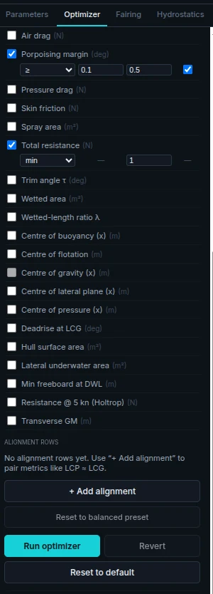
The choices differ per row, because not every mode is meaningful for every quantity — skin friction and pressure drag can only be given a ceiling, for instance. The hard checkbox appears only on ≥ and ≤ rows, since it is only those that express a constraint the solver can be held to.
- Weight — how much this row matters relative to the others. Only meaningful for soft rows.
- Hard — makes it a true constraint rather than a preference. The solver will refuse to return a hull that breaks it, and will report the problem as infeasible if it cannot satisfy everything at once.
After a run, each row gets a badge — weak, balanced, dominant or hard — telling you how much it actually influenced the answer. A row marked weak is doing nothing; raise its weight or drop it.
The metrics
| Row | Unit | What it is |
|---|---|---|
| Total resistance | N | The whole drag force. The usual thing to minimise. |
| Skin friction | N | The part from water rubbing along the wetted surface. |
| Pressure drag | N | The part from lifting the boat — an unavoidable cost of planing. |
| Air drag | N | The part from pushing the topsides through air. |
| Spray area | m² | How much hull is wetted by spray rather than solid water. |
| Wetted area | m² | The planing surface actually in the water at speed. |
| Hull surface area | m² | The total skin area — drives material cost and shell weight. |
| Porpoising margin | deg | Headroom below the pitch-instability limit. See above. |
| Trim angle τ | deg | The running trim at speed. |
| Wetted-length ratio λ | — | Wetted length divided by beam. A slenderness measure for the planing surface. |
| Centre of pressure (x) | m | Where the hydrodynamic lift acts. |
| Centre of gravity (x) | m | Where the weight acts. |
| Centre of buoyancy (x) | m | Where the static buoyancy acts. |
| Centre of flotation | m | The pivot of the waterplane. |
| Transverse GM | m | Roll stability. Offers max and ≥ — this is how you optimise for a boat that does not lean. |
| Min freeboard at DWL | m | The lowest point of the sheer above water. Constrain this to stop the optimiser sinking your gunwale. |
| Resistance @ 5 kn (Holtrop) | N | Low-speed drag, from a displacement-regime method. Useful if the boat must also behave at harbour speeds. |
| Lateral underwater area | m² | Side area below water — course keeping. |
| Centre of lateral plane (x) | m | Where that side area is centred. |
| Deadrise at LCG | deg | The bottom V-angle at the point the weight acts. |
Alignment rows
+ Add alignment pairs two comparable metrics with ≈, ≥ or ≤ and a tolerance. The classic is LCP ≈ LCG: make the lift act where the weight acts, so the boat runs at the trim you intended instead of fighting itself. A live δ pill shows the current gap.
Running it, and reading the log
Press Run optimizer. The Solver Log fills with timestamped lines from both the app and the solver — what it started from, what it is trading against what, and how it ended.
1440 × 900 — drop into static/shots/optimizer-log.webp
When it does not work
| Outcome | What it means | What to try |
|---|---|---|
| Iteration limit | It ran out of steps before settling. | Usually the hull is far from anything sensible, or a range is pathologically tight. Loosen something. |
| Infeasible | Your hard constraints cannot all be true at once. | Turn the least important hard row soft, or widen its bound. The log names what it was fighting. |
| Error | The geometry broke the physics — e.g. a chine above the waterline everywhere. | Look at what you last changed in the section view. |
One run at a time, per server. If someone else in your workspace is solving, you will be told to wait rather than being silently queued.
Overlays
Three checkboxes change what the viewports draw:
- Show optimizer's view (control polygon) — the raw points the solver sees, rather than the smooth surface you see.
- Show planing wetted area (λ section) — the patch of hull actually in the water at the design speed. Greys out until the equilibrium converges.
- Show faired hull shape paid plan — the smoothed surface the exporter would produce.
Alongside them, markers for LCG, LCP, LCB, LCF and LCLP with their live values — the quickest way to see whether the boat is in balance.
Auto-fairing paid plan
Hand-editing points leaves lines slightly lumpy. Fairing pulls the lumps out by minimising the bending energy of the curve — the mathematical version of springing a batten along the hull and letting it find its own shape.
"Pins, ranges, hard kinks, and transom/bow geometry are honored unless overridden below."
The controls
- Fair entire hull — one press, and the server iterates to a stable answer rather than making you click repeatedly. If it reports that it converged, pressing again will not move the hull; if it stopped at the pass cap (see below) it still has work left and a second press will do more.
- Strength — 0 to 1, labelled identity → quintic → cubic → quadratic → straight line. Low values tidy; high values replace your curve with something much simpler. At the top of the range you are asking for a straight line, and you will get one.
- Per-line axes — every longitudinal line gets its own Y and Z checkbox, so you can fair the sheer vertically without touching its half-breadth.
- Station range — restrict fairing to a stretch. The endpoints are held so the faired part blends into the rest. Minimum three stations.
- Section curves — multi-select three or more points in the section view and fair across them instead of along the hull.
- Ignore-constraint toggles — temporarily suspend pins, ranges or inter-point constraints for this fair only. The flags stay on the points; they are just not applied.
Pareto sweep
For when two things you want are in conflict — less drag and more stability, say. Pick Axis A and Axis B, set Grid (3–10), and press Run Pareto sweep.
Grid is how many designs to try, not a grid per side: it walks the balance between your two axes in that many steps, from almost-all-A to almost-all-B, running one full optimisation at each. Ten is ten solves, and the panel estimates the time before you commit.
The scatter plot shows the runs that succeeded — faded for dominated (another design beat it on both axes), solid for the Pareto front, the set where you cannot improve one axis without giving up the other. Runs that came back infeasible are not plotted; they are reported as a count in the corner. Ringed points marked K1, K2, K3 are the knees: where the trade rate changes most sharply, which is usually where the sensible compromises live. Each has a load button to pull that hull into your project.
Speed sweep paid plan
A per-knot table for the current hull: one full equilibrium solve at every speed in the range you set. This is how you find out where the hump is and how much power you actually need.
Set Min (kn), Max (kn) and Step, then Run sweep. Up to 200 rows. Chart opens the same run as a plot.
Three summary pills sit above the table. hump is the transition hump — the speed where resistance peaks and then falls as the hull climbs onto plane. That is the power needed to get on plane. peak is the highest resistance anywhere in the range you swept, which for a planing hull is normally just your top speed — the power needed to hold it. They are different questions and sizing an engine needs both answered. min planing is the lowest speed the boat planes at at all.
| Column | Meaning |
|---|---|
| kn | Speed. |
| τ° | Running trim. |
| λ | Wetted-length ratio. |
| R_tot N | Total resistance. |
| EHP kW | Effective power — drag × speed. The power to move the hull, before propeller and drivetrain losses. |
| L_w m / S_w m² | Wetted length and wetted area at that speed. |
| trim° | Required motor trim; a * means it hit a limit. |
| status | Whether the row is trustworthy — see below. |
Charting the sweep
The table answers "what is the number at 18 kn". Chart answers the other question — what shape is the curve. It plots speed across the bottom and any of the sweep's metrics up the side, including several the table has no column for: Cv, CL β, Vm, LCP, LCP residual and the friction/pressure split of the total resistance.
The Metrics list on the right is picker, key and readout at once: click a metric to show or hide it, and each row carries its value at whatever speed the crosshair is on. A metric the run produced no value for at any speed — the motor-trim figures with no outboard configured, or the friction and pressure split where the resistance blend withheld it — is not offered, and the list says how many were left out. Up to eight series at once.
The side axis changes meaning with how much you select, because these metrics are not on remotely the same scale — resistance runs to thousands of newtons while trim is a handful of degrees. One metric selected gives that metric's real units. Two gives a left and a right axis, each drawn in its series' own colour so you can tell which belongs to which. Three or more can only share an axis by being normalized — each series rescaled to its own range, so the shapes stay comparable but the side axis no longer reads in any unit. The caption under the plot always says which of the three you are looking at, and real values stay in the readout.
If the geometry changes after a sweep, the table is marked geometry changed — table is stale. Re-run it.
A workable routine
- Get the weights roughly right first. Optimising against the wrong displacement wastes the run.
- Publish a version, so you can always get back.
- Pin what you have decided — the keel line, the sheer height, anything driven by the layout.
- Run Balanced at your real cruise speed.
- Read the log and the badges. Anything weak is not earning its place.
- Look at the hull. If the optimiser has done something silly, that is a missing constraint, not a bug — add it and re-run.
- Fair the result before exporting.