Reading the numbers
The Hydrostatics tab is the app's report card on your hull. It is long — this page goes through it group by group and says what each row is for and, where there is one, what a healthy value looks like.
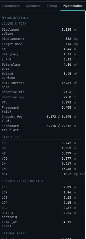
Volume & form
How big the boat is and how much water it is displacing.
| Row | Meaning |
|---|---|
| Displaced volume | The volume of water the hull pushes aside, in m³. |
| Displacement | The same thing as a mass — what the hull is currently lifting. |
| Target mass | What you said the boat weighs, from the Weights modal. This and the row above should agree. |
| LWL | Waterline length — the length actually in the water, always less than the overall length. |
| Bwl (max) | The widest the boat is at the waterline. |
| L / B | Length over beam at the waterline. Higher is slimmer: easier to push, less stable, less room. |
| Waterplane area | The area of the shape the boat cuts out of the water's surface. Drives how much it sinks per extra kilo aboard. |
| Wetted surface | Hull area in contact with water. Directly proportional to friction drag — the dominant drag at low speed. |
| Hull surface area | The whole skin, wet and dry. This is what your material cost and shell weight scale with. |
| Deadrise mid / Deadrise avg | The bottom V-angle amidships, and averaged over the hull. |
| DWL | The height of the waterline the boat settled at. |
| Freeboard (mid) | Waterline to gunwale amidships. Under ~0.2 m on a small boat is getting wet. |
| Draught fwd / aft | How deep it floats at each end. Different values mean it is trimmed. |
| Freeboard fwd / aft | The same at the gunwale. The forward number is the one that decides whether you take water over the bow. |
| Hull volume fwd/aft of cockpit | Only with a cockpit. Useful for thinking about buoyancy in a swamping. An enabled outboard well is subtracted — see the next row. |
| Outboard well recess | Only with an outboard well. How much enclosed volume the motor well takes out of the hull, already deducted above. Note that the transom cutout also means the aft compartment is open, not sealed. |
Stability
| Row | Meaning |
|---|---|
| KB | Height of the centre of buoyancy above the keel. |
| BM | How far the metacentre sits above the centre of buoyancy. Driven almost entirely by waterline beam — this is why wide boats are stiff. |
| KG / VCG | Height of the centre of gravity above the keel. The number you lower by putting heavy things low. |
| GM | The headline stability number. KB + BM − KG. Judged against the waterline beam rather than in bare metres, because GM scales with beam — the readout calls it tender under 0.07 × B and stable above 0.20 × B, and the wizard calls it snappy above 1.25 × B. On a small skiff that works out around 0.3–1.5 m. |
| GM_L | The same idea in the fore-and-aft direction. Always much larger — boats resist pitching far more than rolling. |
| MCT | Moment to change trim. How much twisting effort it takes to alter the trim by one centimetre — a direct measure of how sensitive the boat is to where you put weight. |
Centres (longitudinal)
Where things act, measured along the length of the boat. Getting these to line up is most of what "balancing a design" means.
| Row | Meaning |
|---|---|
| LCB | Longitudinal centre of buoyancy — the middle of the underwater volume. |
| LCF | Centre of flotation — the middle of the waterplane, and the point the boat pivots about when it trims. |
| LCG | Centre of gravity — the middle of everything the boat weighs. |
| LCP | Centre of pressure — where the hydrodynamic lift acts when planing. Matching this to LCG is the key to a boat that runs at the trim you designed for. |
| LCLP | Centre of the underwater side area. Relevant to how the boat tracks and turns. |
| Hull X centroid | The geometric middle of the hull skin, regardless of loading. |
| Trim (at rest) | The result of all of the above: how many degrees off level it sits, stopped. |
Lateral plane
The side-on underwater silhouette — what resists the boat being pushed sideways, and therefore how it tracks and turns.
- Lateral plane area — bigger resists yaw and tracks straight; smaller turns more willingly.
- LCLP − LCG — the lever between the side area and the weight. Large offsets make a boat want to weathercock.
- Effective lateral plane area / Effective LCLP — the same with the outboard's underwater area included, if you have configured one.
Stability & form
Coefficients — dimensionless numbers that describe the shape of the hull independently of its size, so you can compare your boat to others.
| Row | Meaning | Typical |
|---|---|---|
| Porpoising τ_crit | The trim angle at which pitch instability starts. | — |
| Porpoising margin | How far below that limit you are running. This is the number the optimiser's Stability target protects. | Positive. |
| Porpoising flag | A pill: STABLE above 1.5°, MARGINAL from 0 to 1.5°, UNSTABLE below zero. | STABLE |
| Cb (block) | How much of the box enclosing the underwater hull is actually hull. Low means fine and wedge-like. | 0.35–0.50 |
| Cp (prismatic) | How evenly volume is spread along the length. Low means the volume is concentrated amidships and the ends are fine. | 0.55–0.70 |
| Cm (midship) | How full the biggest section is. A deep V is low; a flat bottom approaches 1. | 0.6–0.9 |
| Cw (waterplane) | How full the waterline shape is. Higher gives more stability and more resistance to sinking under load. | 0.7–0.85 |
| A_max (max section) | Area of the largest underwater section. | — |
| T (draft) | How deep the hull goes below the waterline. | — |
| Half-angle of entrance | How sharply the bow parts the water, measured at the waterline. Small is fine and slicing; large is blunt and buoyant. | <20° clean, >35° bluff |
| Transom immersion, Transom / max section, Transom beam / max beam | How much transom is in the water. A planing boat wants a wide transom that the water leaves cleanly; a deeply immersed transom at low speed just drags a hole behind it. | — |
Resistance & planing
On a planing hull this block only fills in when the planing equilibrium converges at your current speed and geometry. It is the answer to "how fast will it go, and what will it take".
On a displacement hull it is replaced by Resistance (Holtrop) below. The rows are not blank — they are absent, because a hull that never rises onto a pressure cushion has no planing trim, no wetted-length ratio and no porpoising limit to report. The Seakeeping block goes with them, for the same reason: it models a planing hull slamming as it re-enters after a wave.
| Row | Meaning |
|---|---|
| Speed | The design speed being solved at. |
| Cv | Speed coefficient — speed made dimensionless against beam. The standard way of asking "how fast is this, for a boat this size". |
| λ (wetted L/B) | Mean wetted length over beam. Above about 4 the planing model stops being valid. |
| CL_β | Lift coefficient for the actual deadrise. |
| Trim τ | The running trim while planing. The sweet spot is usually 3–5°. |
| Required motor trim | With an outboard configured: the trim angle the motor needs to hold this attitude, and whether it hit a limit. |
| Wetted length L_m, Keel-wetted L_K, Chine-wetted L_C | How much of the keel and chine are in the water. The difference between them describes the shape of the spray root. |
| Wetted area (planing) | The pressure area actually carrying the boat. |
| Friction R_f / Pressure R_p / Total R_t | The drag breakdown. Friction is skin; pressure is the price of lift. |
| Spray R_spray / Spray area | Drag from the spray sheet thrown off the bow. |
| EHP | Effective power — drag × speed. Not engine power. A propeller and drivetrain are perhaps 50–65% efficient, so budget the engine well above this. |
| Rise of CG / Running draft | How far the boat climbs out of the water, and how deep it still sits, at speed. |
| Cf (ITTC-57) / Re (wetted) | The friction coefficient and Reynolds number behind the friction figure. |
At low speed the hull is a displacement boat and its drag rises with the wave it makes. As it approaches the speed where lift starts to matter, it is doing both badly at once — still making a big wave, not yet properly lifted — and drag peaks. That peak is the hump.
It is not the most power the boat will ever draw — top speed needs far more. It is the point the boat can get stuck at, which is a different thing: getting past the hump means producing more thrust at a lower speed than the speed just above it requires, so a boat that cannot make that thrust never reaches the easier water beyond.
Push through and the hull rises, wetted area collapses, and drag actually falls before climbing again with speed. An underpowered boat that cannot get over the hump will sit there at full throttle, bow high, going nowhere — a real and common failure. The speed sweep is how you check for it.
Resistance (Holtrop)
A displacement hull's calm-water drag, at the speed set in the Optimizer panel. It comes from the Holtrop-Mennen method (1984) — a regression on towing-tank data for displacement ships — blended with Mercier-Savitsky once you push past hull speed.
| Row | Meaning |
|---|---|
| Fn (length) | Length Froude number, V / √(g·LWL). Hull speed is 0.40. Past it, wave-making climbs steeply. |
| Regime | Which speed band the hull is in, and therefore which method sources the number. Green while the hull is doing what it was designed for. |
| Method | The dominant method and its share of the blend. Holtrop below hull speed, Mercier-Savitsky through the hump. |
| Friction R_f | ITTC-57 skin friction multiplied by Holtrop's viscous form factor. |
| Wave R_w | Wave-making resistance — the term that dominates as you approach hull speed. |
| Transom R_TR | Pressure drag of the immersed transom. Falls to zero once the transom ventilates. |
| Correlation R_A | A roughness and scale-effect allowance. Not hydrodynamic, but a real part of towed resistance — on a 9 m hull at low speed it is the largest of the two smaller terms. |
| Appendages R_APP | Shaft, brackets, rudder, skeg and bilge keels — see below. Zero until you set them up in Parameters → Appendages. |
| Total R_t | The blended resistance at this speed, appendages included. |
| EHP | Effective power: Rtotal · V. What it takes to tow the hull, before propeller and gearbox losses. |
| Validity | Whether your hull sits inside Holtrop's fitted range — see below. |
The four component rows — friction, wave, transom, correlation — show only when Holtrop carries the whole answer. Where two methods are blended they read —, because a split of one method's total against another's would not add up. Appendages R_APP is the exception and always shows: all three methods describe a bare hull, so appendage drag sits on top of whichever one is being used.
What "outside Holtrop's fit" means
Holtrop-Mennen is a regression, not a theory. Outside the range of hull forms it was fitted on it does not fail — it extrapolates, and returns a confident-looking number that can be well off. So the panel tells you, naming the value and the bound: length Froude number above 0.40, prismatic coefficient outside 0.55–0.85, length/beam outside 3.9–9.5, or beam/draught outside 2.1–4.0.
Small beamy launches routinely sit below the length/beam bound — a 9 m boat with a 2.7 m waterline beam is about 3.1. That is a real caveat about the method, not a fault in your hull, and the number is still shown.
Appendages
Shaft, P-bracket, rudder, skeg and bilge keels are fittings, not moulded hull, so they are not in the mesh and no resistance method accounts for them. On a shaft-driven launch they are commonly worth another 5–10% of total resistance, and more than that at low speed — which is why the number used to be a bare-hull figure with a warning attached.
Now you can describe them, in Parameters → Appendages. Pick a kind and give it two dimensions you can measure with a tape — a rudder's chord and span, a shaft's diameter and exposed length, a skeg's length and depth — and the wetted area follows. A shaft is wetted all the way round; a fin is wetted on both faces. Set Count to 2 for a pair of bilge keels rather than entering them twice.
The drag is Holtrop's own appendage formula, ½ρV² · ΣS(1+k₂) · CF, where each (1+k₂) is the drag factor Holtrop tabulated for that kind of fitting. It applies at every speed and under every method, and it is included in the total. You will find it as the speed sweep's Rapp column on any hull, and on a displacement hull also as the Appendages R_APP row here. Leave the panel empty, or switch it off, and every number is exactly the bare-hull figure it was before.
The optimiser treats them the same way, on a displacement hull: its cruise-drag objective is the drag the boat actually tows. A planing hull's objective stays bare-hull, so it remains comparable with the Savitsky resistance beside it — the sweep is where a planing boat's appendage drag shows up.
The caveat. Holtrop publishes several of those factors as a range — 1.5–2.0 for a rudder behind a skeg, 2.0–4.0 for a shaft — and we take the midpoint. That is a real uncertainty of roughly ±15% on the appendage term, which on a fully-rigged 9 m launch is a couple of percent of the total. The friction line is computed on the hull's waterline length, not each fitting's own chord, because that is what Holtrop's factors were fitted against.
On the example set above — a 45 mm shaft, a P-bracket, a rudder behind a skeg and a pair of bilge keels on a 9 m launch — appendages come to about 3% of total resistance at 7 kn rising to 12% at 3 kn. They matter most at low speed, where friction dominates and there is little wave-making to be lost in.
Reserve buoyancy
The volume that is not in the water — what you have in hand if the boat is loaded further, or buries a wave.
- Reserve buoyancy (total) and (forward) — the forward figure is the one that decides whether a wave lifts the bow or comes over it.
- Bow freeboard — height of the sheer above water right forward.
- Flare forward (mean) — the average topside angle up front. Flare converts a bow burying into lift.
Seakeeping (rough-water)
An estimate of how hard the boat will hit in waves, at the design speed, for a list of wave heights.
- k_yy (pitch gyradius) — how spread out the weight is fore-and-aft. Set it in Parameters or accept the computed default, which is measured from the real mass distribution: where every structural part sits, how far each one is spread about its own centre, and where every weight you placed sits. The hull shell and the deck run the whole length of the boat, so their spread is most of the answer. For a conventional planing hull the number usually lands between about a fifth and a third of the length.
- One row per wave height, giving the vertical acceleration at the centre of gravity (CG) and at the bow (bow), in g, with a comfort pill: COMFORTABLE under 0.4 g, FIRM from 0.4 to 0.8 g, PUNISHING at 0.8 g and above.
Both figures are averages, not peaks. Individual impacts in a seaway run several times the average; Hull does not predict them, and the two numbers in a row are two places on the boat, not an average and a worst case. The bow figure is always the worse of the two — it is why passengers sit aft in a chop.
Per-station tables
At the bottom, the same quantities broken out station by station: immersed section area, half-beam at the waterline, section area above water, freeboard and flare angle. Use these to find the one station that is out of step with its neighbours — a bump in the immersed-area curve is exactly the sort of thing fairing fixes.
The Weights modal
Reached from Weights in the top bar, or Edit weights → in Parameters. This is where the mass in every calculation above comes from.
Hull material
One density in kg/m³ for the whole boat. Every part weighs that density times its own thickness or section, so each dimension in Parameters → Construction drives exactly the part it belongs to and nothing else. The planking thickness weighs the hull side and the deck; the transom thickness weighs the transom; siding × molding weigh the timbers.
Hull shell
The material times the planking thickness gives an areal density in kg/m², and that times the computed skin area gives the mass — so thicker planking is a heavier boat. The panel shows the kg/m² as a readout beneath the material. The mass is applied at the geometric centre of that skin — fore-and-aft and in height — so it moves as the hull shape changes. For the rough-water estimate Hull also measures how far the skin is spread about that centre, since a shell running the length of the boat resists pitching far more than the same weight in a box amidships would.
The skin area is measured round each station and along the boat. The Hull shell figure covers the bottom and the topsides — keel up to sheer. The deck is measured the same way but priced separately, below. The transom and the backbone are not skin at all and have their own rows.
Deck
Sheer inboard to the centreline, swept along the boat. On a 6 m skiff that is about half the total skin area, so it gets a density of its own — decks are often lighter stock than topsides. Left alone it matches the hull shell, which is what it has always been. Set it to 0 for an open boat.
Transom
The transom is a plate, not skin, so it is weighed on its own: its true panel area times the hull material over its own thickness, set in Parameters → Construction — 2000 kg/m³ over a 19 mm transom is 38 kg/m². The planking thickness does not enter; the plate has a thickness of its own. Read the resulting area and mass in the Transom card; change the number in Parameters.
Backbone
The keel and the stem are timbers, not panels, so they are weighed by their cross-section rather than their area: siding × molding from Parameters → Construction — the same two numbers that have always driven the keel & stem schedule — times the run length the app measures off your hull, at the hull material. So 2000 kg/m³ makes a 60 × 120 mm keel 14.4 kg/m. As with the transom, the planking thickness does not enter: the timber has a section of its own.
A part you have chosen not to build reads differently from one that cannot be worked out. Zero the transom thickness or a timber section and the row says not weighed against a real 0 kg; clear the hull material and it says needs a hull material against a dash. The first is your decision, the second is a missing input.
Placed objects
Click empty space on the plan view to add one; drag it to position it fore-and-aft and athwartships; set its mass and its height in the side panel. Engine, fuel, batteries, crew.
Mass summary
Written as the addition it is. A row for each part — hull side, deck, transom, keel + stem — which add up to Structure; that plus Objects is the Total mass and its LCG. Structure against payload is the split worth watching: a hull that is 70% structure is a hull with no carrying capacity left. Then Expected DWL and Trim · freeboard — the app re-solves where the boat floats every time you move something. The LCG and LCB markers on the plan view are the quick visual check: line them up and the boat sits level.