The design lab
Where the actual design work happens. This page is a tour: what is on the screen, how to move the hull around, and how to tell the optimiser what it is and is not allowed to touch.
How a hull is stored
Everything in the designer makes more sense once you know the data model, and it is simple: a hull is a grid of points.
Down the length of the boat there are stations — transverse slices, like the frames of a real boat. Each station carries the same number of points, and point number j of every station belongs to longitudinal line number j. Seven lines come as standard.
You can add more lines wherever you want them — a spray rail, a reverse chine — by splitting the gap between two existing points. See adding a longitudinal line below.
What is on the screen
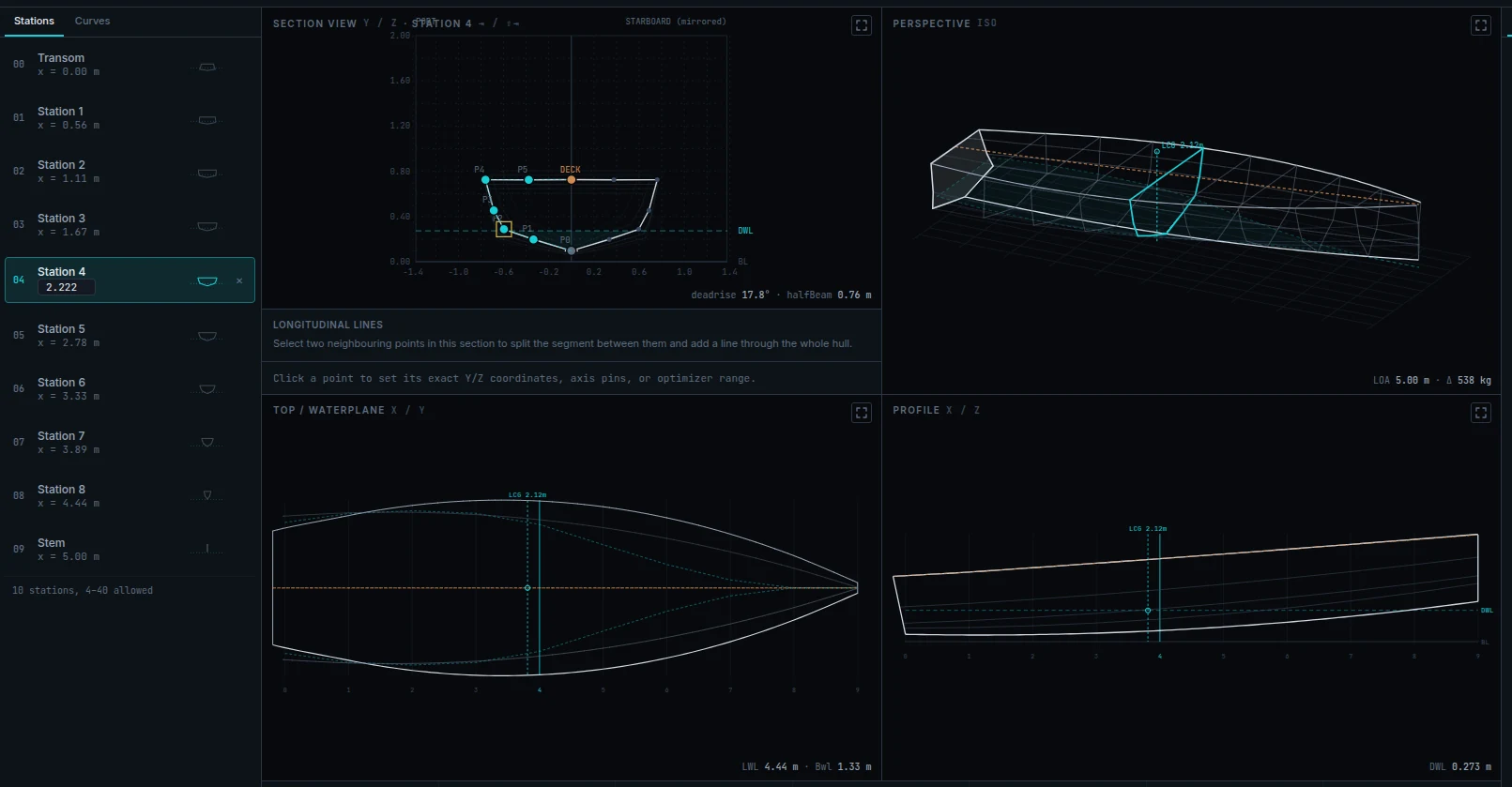
The top bar
- The brand on the left is a link back to your projects.
- The project name, then a pill showing saving… or saved. There is no save button — see auto-save.
- Versions, Export, Weights, 3D preview, and Optimize on the right.
Two banners can appear here. viewing published v3 — read-only means you have opened a frozen version: look all you like, but editing, optimising and auto-save are off until you press Continue work from this version. And connection lost — retrying… your changes are kept means the backend went away; keep working, the app will catch up.
The four viewports
| View | What it shows | What you can do |
|---|---|---|
| SECTION VIEW y / z | One station, seen from ahead. The working view. | Drag control points. Multi-select. Everything else is a read-out. |
| PERSPECTIVE iso | The whole hull in three dimensions. | Drag to orbit. |
| TOP / WATERPLANE x / y | Looking down: the waterplane, the chine (or turn of bilge), the cockpit. | Read-only, but you can hover the highlighted line for coordinates. |
| PROFILE x / z | The side view, including a raked transom. | Read-only, but you can hover the highlighted line for coordinates. |
The whole-hull views can carry overlays. The Optimizer tab toggles the optimiser's control polygon, the faired surface, and the planing wetted patch — the last of these draws on the PERSPECTIVE view only. The highlighted line is separate: pick it under Parameters → Editor → Highlight line, or cycle it with h.
With a line highlighted, hover it in TOP / WATERPLANE or PROFILE: a marker pins itself to the curve under your cursor and reads out that point's x, y and z in metres. It follows the curve continuously, so you can measure between stations — the half-beam a third of the way forward, say — without adding one. Each view reports the coordinate it cannot draw: TOP / WATERPLANE gives you the height, PROFILE the half-beam. Because the plan view draws both halves of the hull, its reading is tagged port or stbd. Move away from the line and the readout disappears.
Editing a section
Pick a station from the list on the left (or step through with the arrow keys), then drag its points in the SECTION VIEW. You are moving the point athwartships and vertically; its fore-and-aft position is fixed by the station it belongs to.
- Snap. Snap to grid in the Parameters tab rounds every drag to 1cm or 5cm. Useful once you are tidying up rather than exploring.
- Ghosts. Faint outlines of the neighbouring stations are drawn behind the one you are editing, so you can see whether your change makes the hull lumpy fore-and-aft.
- Multi-select. Hold Shift, Ctrl or Cmd and click to select several points — needed for fairing a stretch of a section curve.
- Locked points do not move. If an axis is pinned, drags on that axis are ignored. This is deliberate, not a bug.
The point inspector
Click a point and the inspector appears below the section view. This is where precision lives — and where you tell the optimiser what it may do.
Exact coordinates
Y axis and Z axis each get a numeric field in metres. Type a value and press Enter; Esc cancels.
Pins — 🔒
A pin locks that axis. The point cannot be dragged on it, and the optimiser and the fairing tool will not move it either. Pin the things you have decided: a keel that must stay on the centreline, a sheer height that has to clear a deck fitting.
Ranges — ↔
A range gives the optimiser a band to work inside — a minimum and a maximum for that axis. Turning it on seeds a band around the current value — 0.10 m on a small hull, wider in proportion on a big one — which you then edit.
Kinks — ◆
Two independent toggles, and the distinction matters:
- section — a hard corner in this cross-section, at this station. A planing hull's chine has this on by default; a displacement hull's turn of bilge has it off, and that single flag is the whole difference between the two shapes.
- long — a hard corner in the longitudinal line running through this point, fore-and-aft.
Without a kink the surface curves smoothly through the point. With one, it is allowed to break — which is exactly what you want at a chine, and exactly what you do not want in the middle of a topside.
Constraints
Rules that tie one point to another within the same station — for instance "P2 must sit 0.05–0.10 m outboard of P1", which is how you describe a chine step that must not close up.
Press + add, pick the axis, the reference point, the direction (outside/inside for Y, above/below for Z) and the minimum and maximum. The rule then reads back in plain language, and shows ⚠ violated if the current geometry breaks it, or 🚫 frozen if both endpoints are pinned so nothing could satisfy it.
Stations
The list on the left. Each row is one transverse slice, with its name, its fore-and-aft position, and a thumbnail of its shape.
- Move one. Click the x = … value on the active station and type a new one. It must stay between its neighbours; if you overshoot, the app clamps it and tells you it did.
- Insert one. The + button between two rows. The new station is seeded from the faired surface, so it lands on the shape you can already see rather than on a straight line between neighbours.
- Delete one. The × on the row. The transom and the stem cannot be deleted or moved.
- How many. Between 4 and 40. The footer shows the current count.
Uneven station spacing is allowed, and it has one consequence worth knowing: the volume integration switches from Simpson's rule to the cruder trapezoid rule if adjacent gaps get too lopsided. When that happens it is stated in the hydrostatics output rather than silently changing your numbers.
Adding a longitudinal line
Under the section view, the Longitudinal lines card: "Select two neighbouring points in this section to split the segment between them and add a line through the whole hull."
- Shift-click two adjacent points in the section view.
- Set Position — where between them the new line goes, 10–90%.
- Name it, for example Spray rail.
- Press Split segment.
The new line is added at every station at once, so the mesh stays rectangular. It is a full citizen: you can pin it, range it, kink it, fair it, and the optimiser will move it. It appears in the offsets export under the name you gave it.
To remove one, select a point on it and press Remove "name" from every station. The seven standard lines cannot be removed.
The Parameters tab
Settings that belong to the boat rather than to any one point.
| Group | What is in it |
|---|---|
| Loading | A shortcut into the Weights modal. |
| Hull form | Transom rake, −60 to 60°. Positive leans the transom aft at the top, pivoting at the keel. Affects the at-rest hydrostatics, the CAD export and the profile and 3D views. |
| Outboard motor | Lateral area and position, prop depth, setback, trim limits and a prop lift factor. These feed the required-motor-trim solve and the course-keeping numbers. With a motor enabled you can also cut an outboard well — a recess and a transom cutout, with a live check that the mount height fits between keel and deck. The recess is not enclosed hull, so its volume comes off the Hull volume aft of cockpit figure in the Hydrostatics panel. |
| Construction |
Every dimension here is a real part, and each one
carries weight: its own measurement times the
hull material set in the Weights
modal. Nothing here scales anything else.
Thickness (0–50 mm) is the planking. It sets the weight of the hull side and the deck — double it and you have twice the skin — and it shifts the table-of-offsets and keel & stem coordinates inward to the inside of the plank. It does not thin the CAD surface, which is the moulded shape. Transom thickness (0–150 mm, default 19 mm) is a real plate. It is drawn as a plate with its bevel in the 3D view, ships as its own solid alongside the hull in the STEP and OBJ exports, adds the inner-face and bevel rows to the table of offsets, and carries its own weight — cut from the same stock as the skin, so thickening it makes the boat heavier and pulls the LCG aft. Set it to 0 for no separate plate. Keel siding, Keel molding, Stem siding and Stem molding are what the keel & stem CSV export is checked against — and, since they describe a real cross-section, they carry weight too: at the default 2000 kg/m³ a 60 × 120 mm keel is 14.4 kg per metre of run. Set a siding or a molding to 0 if you are not building a timber backbone. See the Weights modal. |
| Editor | Snap to grid, Mirror to starboard, and Highlight line — which draws one longitudinal line boldly in every view so you can follow it down the hull. |
| Cockpit | Position, length, insets fore and aft, corner radii, sole height and coaming drop. More control than the wizard offers. |
| Appendages | Shaft, brackets, rudder, skeg and bilge keels — the fittings that are not part of the hull mesh. Each row is a kind plus two dimensions you can measure with a tape; the field labels change to suit the kind you pick, and the panel shows the wetted area and drag factor it derives. Feeds the appendage drag — shown as the speed sweep's Rapp column on any hull, and additionally as the Hydrostatics panel's Appendages R_APP row on a displacement one. Empty by default, so an untouched project reports a bare hull. |
| Dynamic-prediction assumptions | Pitch gyradius and the list of wave heights used for the seakeeping estimates. Leave them blank to accept the computed defaults. |
Keyboard shortcuts
| Key | Does |
|---|---|
| ← → | Step to the previous or next station. |
| Tab / Shift+Tab | Cycle the active station, wrapping at the ends. |
| h / Shift+H | Cycle which longitudinal line is highlighted. |
| Esc | Restore a maximised viewport; cancel a numeric edit in progress. |
| Enter | Commit a numeric field. |
| Shift/Ctrl/Cmd + click | Add a point to the selection. |
Shortcuts are ignored while you are typing in a field.
Auto-save
Every change is saved about a second after you stop making it. The pill by the project name shows saving… then saved.
- After an optimiser run the save is immediate, not debounced — a crash cannot cost you a solve.
- A failed save is retried with a growing delay, always sending your latest state rather than the stale attempt.
- Read-only mode (viewing a published version) turns auto-save off entirely.
The 3D preview
The 3D preview button opens a shaded, orbitable model with a choice of finishes — Gray, Light wood, Dark wood, Metal, White. It is built when you open it and is not live, so reopen it after making changes.