Export, versions & sharing
Getting the design out of the app — as CAD geometry, as numbers to build from, as a frozen reference, or as something a colleague can open.
CAD export
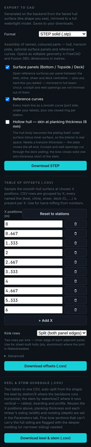
The Export tab. Everything is generated on the server from the faired hull surface — the shape you see — and mirrored to a full watertight model.
| Format | What it is | Reach for it when |
|---|---|---|
| STEP solid (.stp) | An assembly of named, coloured parts — the hull and transom plate, plus optional surface panels and reference curves. Opens as editable geometry in FreeCAD or Fusion 360, in metres. | You are taking the design into CAD to detail it. This is the one you usually want. |
| IGES wireframe (.iges) | Station rings and longitudinal lines as curves. No surface. | Something downstream wants curves rather than a solid. |
| DXF wireframe (.dxf) | Station rings and longitudinal lines, on STATIONS / LONGITUDINALS layers (plus TRANSOM when a plate is set). Lightweight lines plan. | You want a traditional lines plan to print or trace. |
| OBJ mesh (.obj) | Triangulated watertight shell — visual or 3D-print, not editable surfaces. | You want to look at it, render it, or print a model. Opens in anything. |
OBJ is built from that same kernel when it is available, and falls back to a simpler hull-only mesh when it is not — so the file always downloads, but a deck, cockpit and outboard well will only be in it if the kernel is there. DXF needs a separate (small) library. Both CSV exports depend on nothing and always work.
What is in the STEP file
The STEP is an assembly: a root product named after your project, containing named, coloured parts a CAD tree shows individually. Hull is always there; Transom plate joins it when a Transom thickness is set. Two checkboxes under the format picker add reference geometry to design against:
- Surface panels (Bottom / Topside / Deck) — one open surface per panel of the hull, split where the section breaks: at the keel, chine, sheer and deck centreline, plus any hard line you added. A hard line splits its panel and the pieces say between which lines they run — add a hard Spray rail below the chine and you get Bottom (Keel-Spray rail) and Bottom (Spray rail-Chine). The panels are the uncut moulded surface, mirrored to full beam: cockpit and well openings are not trimmed out of them, because a reference surface you loft a console or a stringer against should not have holes in it.
- Reference curves — every mesh line as a smooth curve under your own labels (Keel, Chine, Sheer, a renamed aux line under its name), port side, plus one closed ring per station named with its position (Station 3 (x = 2.00 m)). Project them into sketches, measure against them, or loft new parts through them.
Both are on by default; untick them for the smallest file. The hull solid itself is exactly the watertight solid it always was — the parts and names are added around it, not carved out of it.
Hollow hull — the plating as a solid
The Hull body is normally the moulded volume: boat-shaped space, filled solid. Tick Hollow hull — skin at planking thickness and it becomes the plating itself — the outer surface minus an inner surface one planking thickness inside it (Parameters → Construction, 6 mm by default), so the interior is real space to model tanks, soles and furniture into. Section it in CAD and you see the walls.
- It needs a transom thickness: a hollow shell cut square at the transom would gape there, so the transom plate — which stays a solid part — is what closes the aft end. Without one the export refuses with a message saying so.
- Openings stay openings. A cockpit or motor-well recess becomes a genuine cutout through the deck plating; coaming and sole plates are not modelled — that interior is yours to design.
- The bow closes solid one skin thickness short of the stem (the planking meets there; a stem timber is not modelled), and earlier on a bow too fine to carry the skin — the export log says where.
- The inner surface is built the way the offsets table's inner-face rows are, so it is the same inner mould line your CSV shows. On the default skiff the hollow hull weighs in at 138 litres of plating against a 2.2 m³ moulded solid.
The transom comes out as its own part
Set a Transom thickness in Parameters → Construction and the STEP and OBJ files arrive as two mating pieces instead of one: the hull, stopping at the plate's inner face, and the transom plate that fills the gap. Put them back together and you have exactly the shape you drew, so nothing is invented and nothing is lost — but you can now select the plate on its own, bevelled on every edge, and take it straight to a cutting list. In STEP it is the named part Transom plate in the assembly; in OBJ they are named objects (transom is the plate).
IGES and DXF have no surfaces to bevel, so they get the plate's inner outline as one more curve at the transom. The gap between that curve and the transom section is what you cut away.
Leave the thickness at 0 and each format carries one piece again: a single solid (the assembly then holds just Hull), one outline.
Table of offsets
The traditional way of describing a hull in numbers, and what you want if you are lofting by hand rather than cutting from CAD.
"Sample the smooth hull surface at chosen X positions. CSV rows are grouped by X; every named line (keel, chine, sheer, deck-CL, …) is present per X."
Choosing where to sample
An editable list of X positions along the boat, with + Add X and Reset to stations. You are not tied to your design stations — put the sample points where your moulds go.
Kink rows — the one setting to get right
At a hard corner like the chine, two different builders want two different things, so you choose:
| Setting | What you get | Suits |
|---|---|---|
| Split (both panel edges) | Two rows at the corner — one for the edge of each panel meeting there. | Sheet building: plywood, aluminium. You are cutting two panels and need the edge of each. |
| Miter (inside corner) | One row, at the corner itself. | Single-skin laminate over a mould, where the corner is a single continuous point. |
Under Advanced, Intermediates per pair (0–8, default 2) adds extra sampled points between each pair of named lines, for a finer table.
What is in the file
Columns: x, y, z, line, section_kink, longitudinal_kink, rake_capped, face, bevel_deg. The line column carries the role names — keel, quarter_beam, chine, half_topside, sheer, half_deck, deck_centerline — plus any lines you added yourself, under the names you gave them.
The coordinates are the inside of the plank whenever Thickness in Parameters → Construction is above zero: the whole table shifts inward along the local surface normal. Leave it at zero to get the moulded (outside) shape.
The transom panel and its bevel
The file carries a developed flat panel block for the transom — the panel unrolled into the plane, so you can cut it from sheet without working out the true shape yourself. It appears whenever the transom is raked or has a thickness.
With a Transom thickness set, every point comes twice: face=outer then face=inner. The outer outline is what you cut to; the inner one is where that same edge lands one plate-thickness forward, which is smaller wherever the hull narrows going forward. Draw both on the sheet and the gap between them is the bevel.
bevel_deg on each outer row gives that angle directly, measured away from square. Positive means undercut — the usual case, where the edge leans in towards the inside of the boat. Negative means it flares out. A chine gets two values, one for each panel meeting there, because the two panels arrive at different angles.
Keel & stem schedule
Two tables in one CSV, split automatically at the point where the backbone stops running horizontally and starts running vertically: the keel tabulated by station, the stem by waterline height. Rabbet, bearding and profile — the numbers you need to cut the backbone timber.
It reads the Keel siding, Keel molding, Stem siding and Stem molding values from the Construction group in the Parameters tab, so set those first.
Versions
"Publishing freezes the hull as it is now into a numbered, read-only version — a reference you can hand to a build or return to later, knowing it won't drift."
Use it before any big experiment, and whenever you reach something you would be sad to lose.
| Action | What happens |
|---|---|
| Publish current version | Freezes the current state as v1, v2, … with an optional description. The project itself stays fully editable. |
| Open read-only | Loads that version into the designer for inspection. Editing, optimising and auto-save are disabled, and the top bar says so. |
| Continue work from this | Copies the version back over your working hull — and snapshots your current state as a new version first, so this is not destructive either. |
| Delete | Removes a published version. Needs manage permission on the project. |
Each version card shows when it was published, by whom, and its headline dimensions, so you can tell them apart without opening them.
Sharing a project
From the project card on your library page, choose Share project, enter an email address, and pick read or write. People you have shared with see the project under Shared with me.
Workspaces
A workspace owns projects, members and the plan. You get one when you sign up, and can create more from the sidebar. Manage members from Settings → Members: Invite a member by email, revoke a pending invite, or change someone's role.
| Role | Can |
|---|---|
| viewer | Open and read projects. |
| editor | Also create and change them. |
| admin | Also manage members and invitations. |
| owner | Everything, including the workspace itself. |
How many people a workspace can hold is a plan limit — one on free, five on mid, unlimited on top.